Introduction to Ammonia Production
Ammonia is critical in the manufacturing of fertilizers, and is one of the largest-volume synthetic chemicals produced in the world. This article explores the evolution of ammonia production and describes the current manufacturing technologies.
Modern production processes
The tremendous increase in ammonia demand from 1950 to 1980 necessitated larger, more-energy-efficient plants. Those decades also saw a change in design philosophy. Until that time, an ammonia plant was regarded as an assembly of unrelated units, such as gas preparation, gas purification, gas compression, and ammonia synthesis. New innovations and an integral design tied process units together in the most effective and efficient ways.
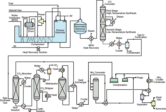 Figure 3. KBR designed one of the first single-train, large-capacity ammonia plants.
In the mid-1960s, the American Oil Co. installed a single-converter ammonia plant engineered by M.W. Kellogg (MWK) at Texas City, TX, with a capacity of 544 m.t./day. The single-train design concept (Figure 3) was so revolutionary that it received the Kirkpatrick Chemical Engineering Achievement Award in 1967.
The plant used a four-case centrifugal compressor to compress the syngas to a pressure of 152 bar, and final compression to an operating pressure of 324 bar occurred in a reciprocating compressor. Centrifugal compressors for the synthesis loop and refrigeration services were also implemented, which provided significant cost savings.
The key differences between the MWK process and the processes used in previous ammonia plants included:
- using a centrifugal compressor as part of the synthesis gas compression
- maximizing the recovery of waste heat from the process
- generating steam from the waste heat for use in steam turbine drivers
- using the refrigeration compressor for rundown and atmospheric refrigeration.
An integrated scheme that balanced energy consumption, energy production, equipment size, and catalyst volumes was incorporated throughout the plant.
Most plants built between 1963 and 1993 had large single-train designs with synthesis gas production at 25–35 bar and ammonia synthesis at 150–200 bar. Another variation by Braun (now KBR) offered slight modifications to the basic design. The Braun Purifier process plants utilized a primary or tubular reformer with a low outlet temperature and high methane leakage to reduce the size and cost of the reformer. Excess air was added to the secondary reformer to reduce the methane content of the primary reformer exit stream to 1–2%. Excess nitrogen and other impurities were removed downstream of the methanator. Because the synthesis gas was essentially free of impurities, two axial-flow ammonia converters were used to achieve a high ammonia conversion.
Some recently built plants have a synthesis gas generation system with only one reformer (no secondary reformer), a pressure-swing adsorption (PSA) system for H2 recovery, and an air separation plant as the source of N2. Improvements in converter design, such as radial and horizontal catalyst beds, internal heat exchangers, and synthesis gas treatment, helped increase ammonia concentrations exiting the synthesis converter from about 12% to 19–21%. A higher conversion per pass, along with more-efficient turbines and compressors, further reduced energy consumption. More-efficient CO2 removal solutions, such as potassium carbonate and methyldiethanolamine (MDEA), have contributed to improved energy efficiency. Most modern plants can produce ammonia with an energy consumption of 28 GJ/m.t.
In addition to the design, mechanical, and metallurgical improvements made during this time, the operating pressure of the synthesis loop was significantly reduced. When the first single-train plant was built in the 1960s, it contained a high-pressure synthesis loop. In 1962, MWK received an inquiry from Imperial Chemical Industries (ICI) for a proposal to build a 544-m.t./day plant at their Severnside site. MWK proposed a 152-bar synthesis loop instead of a 324-bar loop.
Because the development of kinetic data for the ammonia reaction at 152 bar would take more time than MWK had to respond to the ICI inquiry, they contacted Haldor Topsøe to support their plans. Topsøe had data covering the entire pressure range of interest to MWK. In addition, they had a computer program for calculating the quantity of catalyst that was required at the lower operating pressure. Even though ICI chose Bechtel to design the plant, MWK was able to develop a flowsheet for a 544-m.t./day design with centrifugal compressors and a low-pressure synthesis loop, which some people consider the single most important event in the development of the single-train ammonia plant.
Approximately twice as much catalyst was required at 152 bar as at 324 bar, an increase that seemed economically feasible. Although the converter would need twice the volume, the lower operating pressure would reduce the required thickness of the pressure shell. As a result, the weight of metal required for the converter plus the catalyst remained about the same. The lower-pressure synthesis loop also allowed the use of centrifugal compressors instead of reciprocating compressors. Another improvement was recovering heat to generate high-pressure steam for steam turbine drives.
Plant designs in the 21st century
During the first few years of the 21st century, many improvements were made in ammonia plant technology that allow existing plants to increase production rates and new plants to be built with larger and larger capacities. Competition between technology suppliers is quite fierce. Three technology licensors — KBR (Kellogg Brown and Root), Haldor Topsøe, and ThyssenKrupp Industrial Solutions (TKIS) — currently dominate the market. Ammonia Casale, which offers an axial-radial catalyst bed design, is a market leader in revamps of existing plants.
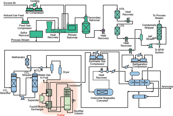
Figure 4. Modern ammonia plants designed by KBR employ its proprietary Purifier design.
https://www.aiche.org/resources/publications/cep/2016/september/introduction-ammonia-production
Comment
10/5/2020 12:45:16 PM
10/5/2020 12:46:42 PM